
Just a few weeks ago, while looking several chinese websites for electronic parts, in some of them I noticed several offers of different models of 3D printers for less than $200. Generally, I always ignored these offers, since, although I wanted to have in my hands one of these, the cost still seemed excessive for something that I would only use, maybe, from time to time, in addition, many of these 3D printers are very big, and my house is not exactly big. But between all of them, one of these could spark my interest by price and size. A small 3D printer, more or less portable, and for less than $140 ($139.90 to be exact). And after a few days of thinking about it (and looking well at my budget) I made the decision to acquire one. This decision was made knowing that I was going to acquire a chinese product, perhaps of dubious quality, and assemble it by myself with all the good and bad details associated with it.
Unpacking
The box with the unarmed 3D printer arrived a month after it was purchased from Gearbest. It was supposed to arrive in the week, but for mysterious reasons, that post was delayed several times by … availability problems?

The box, approximately 4.5Kgs, contained two trays of expanded polystyrene, both containing all parts of the 3D printer, but that still remained to be seen. Among all parts and pieces, it was something like a USB stick, in this case a USB adapter for microSD memory cards. In this memory contains two PDF manuals (assembly and operation of the 3D printer), the USB driver, a copy of Repetier Host, and an .stl file with a test piece design for printing. On the other hand, the assembly parts are basically made of machined black acrylic pieces, black anodized aluminum strips, bearings, traction belts, cables, hoses and a bag with nuts and bolts, and a pair of screwdrivers.
On the electrical and electronic side, there is the preassembled extruder unit, four stepper motors, end switches, a Melzi 2.0 controller card, an LCD display unit, USB cable, and a 12V/5A power supply.
This 3D printer does not come with the hotbed. Although the electronics are prepared to control one, the power source does not have enough power to feed a heater that consumes at least about 8A, so this printer is not capable of printing using ABS filaments.
Assemble
Once both PDF documents are read, I proceed to the assembly of the 3D printer. The instructions are clear and easy to follow, but this is a job for people who are skilled in mechanical matters, and it is good to observe a certain order in the assembly of the different parts so as not to have to disassemble and replace a part because it was necessary to assemble another part previously. So, be patience…

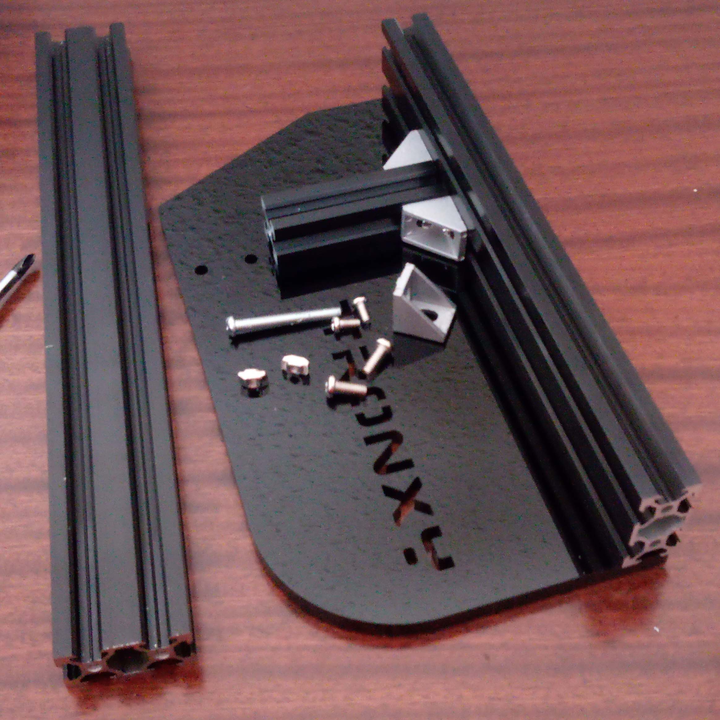
The first step is to assemble the base and side support for the Y and Z axes of the 3D printer.


The next step is to install the Y-axis stepper motor. For this step, the motor, the belt drive shaft, the limit switch, one of the acrylic support bases and several screws are required.


The next step is the assembly and installation of the mobile print base. For this, another of the acrylic parts, three bearings and their respective screws are required.


Then proceed to attach the drive belt and adjusting terminal to the free end of the aluminum profile in front of the printer.


Once installed and adjusted this base, I noticed an annoying error in its design … do not stand firm!
The base is loose and staggers laterally. After tensioning the belt, I did a manual drag test and noticed that the base did not stay perfectly horizontal while moving from one end to the other. This is fatal when it comes to printing. The only thing I could do later was to widen laterally the middle hole between the three bearings (the one on the left in the photo). There is a 1mm error, so with the help of a small drill, I proceeded to widen the screw hole 1mm to the right (towards the other two bearings on the right) as perpendicular as I could towards to the axis. Then, with a little effort, I tighten the bearing against the shaft while tightening the nut, making the base stable and without lateral jumps. However, this is a temporary solution, and I will need to make a new basis with that correction.
Once this problem is solved, proceed to assemble the X axis, which corresponds to the extruder. For them it is necessary the third aluminum profile, three bearings, an acrylic base and a metal base, which will later support two stepper motors, the displacement of the head, and the extruder.


The next step is to place the stepper motors for the X axis and Z axis. The latter is placed in the base of the 3D printer, just below the newly assembled structure. We start with the Z axis.

To support the stepper motor in the base, a piece is used which, incidentally, is printed in 3D, but has details of curvature (warping), which, as we will see later, will give us some problems.

Another annoying detail is that, despite the large number of screws that facilitate, just the 4 screws are missing to fix the stepper motor to the base. This problem could be solved using screws that were available from another machine and that coincidentally correspond to the thread (but not the size) to fix the motor. Very bad detail…


The support part of the stepper motor is twisted, which leaves a free space between it and the motor as can be seen in the photo

Then proceed to install the Z-axis offset screw and the transmission cylinder.


More annoying details. The screw is too tight, and is in part a combined problem between the motor base and the bending angle of the X-axis support structure. The only quick solution I found for this was to loosen two of the three screws support.

Next, mount the extruder head


New problem, the X-axis arm is not perfectly horizontal and there is mechanical play up and down. Again, there is an error in the distance between the bearings of approximately 1mm. In this case I can not solve the problem using the drill because the bearings are screwed to the metal base of the support structure. After a little thought, the only thing that occurred to me to solve this quickly was to wrap the medium bearing with duc tape as shown in the photo. After this, the shaft was perfectly straight and firm, and smooth movement.

Next, install the extruder drive mechanism. The tension and drag mechanism is quite simple, in fact, too.

In my opinion, this mechanism could have been much better, since it is held barely using the same screws to hold the stepper motor


We connect the teflon tube between the drive mechanism and the extrusion head and thus complete the assembly of the X axis

The upper handle and the Z-axis limit switch


To finish the assembly of the mechanics, the printing bed is placed


With this last installation, the mechanical assembly of the printer is finished

In the next publication will proceed to the assembly of the electronic part, its connections and the test of operation.
1 Comment
Excellent thanks